New Oil Analysis Handbook
Third edition contains more How To articles and more case studies
It has been more than two years since we published the first edition of the Oil Analysis Handbook. Our original goal was to compile a comprehensive reference book of common in-service oil analysis techniques to help readers understand and choose the right technique and instrumentation for their needs. Each edition brings us closer to this original goal.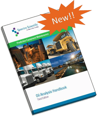
In-service oil analysis for condition based maintenance covers a wide array of topics. We reorganized the structure of the content for better clarity and we added articles to cover more topics and instruments associated with oil analysis. Also, we rewrote several articles including the latest developments in the market. As we learned more from our customers about their successes using on-site oil analysis, we developed case studies that you can find in this edition.
Finally, in-service oil analysis technologies have advanced in the past few years. Innovations in new products have brought on-site oil analysis into the hands of reliability professionals and mechanics. Simple analytical tools enable engineers to make maintenance decisions quicker and with more confidence. We are pleased to share the recent developments in this field and look forward to continued progress.
Please enjoy your complimentary copy of the Oil Analysis Handbook.
The Third Edition of the Oil Analysis Handbook contains:
Oil Analysis Techniques
Elemental Analysis
- Rotating Disc Electrode Optical Emission Spectroscopy (RDE-OES)
- X-ray Fluorescence for large particles
Particle Analysis
- Dynamic equilibrium – large wear particles in oil lubricated systems
- Ferrography – Particle size and morphology analysis
- Particle Count
- Ferrous Particle Analysis
- LaserNet Fines®: Particle count, particle shape analysis and ferrous particle analysis
Infrared Spectroscopy
- Direct Infrared Spectroscopy Based on Grating Optics
- FluidScan introduction
- TAN-TBN Measurement Using Infrared Technique
- Water Measurement Using the Infrared Technique
- Dissolved Water Measurement
- Free Water and Total Water Measurement
- Filter based IR
Viscosity
- Laboratory kinematic viscometers
- Solvent free portable viscometer
Fuel Dilution
Applications for Oil Analysis
All - How to avoid lubricant mix up
Industrial Plants and Power Generators - Route-based oil analysis for industrial plants
Mining - equipment maintenance
Trucking - servicing on-the-road transportation vehicles
Oil and Gas - offshore drilling reliability service
Water Treatment - municipal water treatment maintenance
Industrial Plants - oil analysis for industrial plants
Service Providers - reliability service
Power Generation - engine generator maintenance – portable power
Marine - shipboard maintenance
Case Studies
“Gold Mine saves millions of dollars with on-site analysis”
“Municipal Fleet prevents failures with early warning through oil analysis”
“House calls for off-shore drilling platform – bringing oil analysis to the rig”
“Municipal water treatment plant cuts maintenance costs with on-site oil analysis”
“Pulp and paper mill reduces oil costs with on-site oil analysis”
“Power plant avoids costly downtime with on-site oil analysis”
“Bottling plant avoids shutdown by early detection of ferrous wear”
“Portable power generators use oil analysis to extend oil drain intervals”
“Marine vessels use on-board oil analysis to keep equipment running”
On-site Oil Analysis to extend oil drain intervals
Fleets demonstrate ROI on do it yourself oil analysis
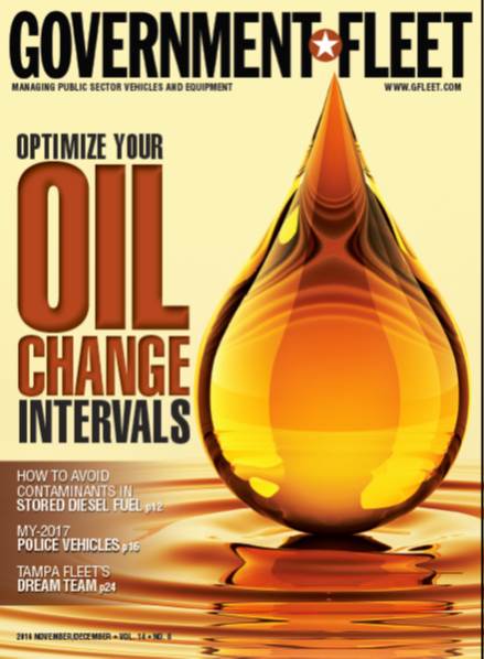
“If the oil is good, why would you change it?” Gary Lentsch, CAFM, fleet manager for Eugene Water & Electric Board (EWEB), asked himself. And more importantly, how much was it costing
him to change oil when it wasn’t needed? Lentsch began asking himself this after he saw an oil analysis machine at a fleet conference. He had been sending out oil for analysis periodically, but an in-house unit would speed up the process and allow him to make drastic changes to the fleet maintenance program. But at a cost of more than $80,000, he was concerned about a return on investment (ROI).
Lentsch isn’t the only fleet manager who has been or is exploring extended oil change intervals and re-examining their fleet preventive maintenance (PM) program. A number of fleets are using oil analysis as a way to extend service intervals and reduce downtime and operating costs.
Correcting Over-Extended Intervals
EWEB has been sending out its oil for analysis at a local lab for years. Its old light-duty PM program consisted of changing oil every 5,000 miles. Using oil analysis, the fleet determined it could extend this to 10,000 miles, with an inspection every 5,000 miles.
In July, the utility purchased an oil analysis machine that could analyze multiple vehicle fluids. Data from the machine helped the fleet see that perhaps it had over-extended its oil change intervals. With the ability to conduct nearly instant readings at every service, fleet staff saw total base number (TBN) levels in the oil were low when vehicles came in at 10,000 miles.
To compensate, the fleet is switching from a synthetic oil blend to full synthetic to make it to 10,000 miles, with the hope of extending it out to 15,000 miles. However, vehicles still get inspected every 5,000 miles, 300 hours, or within six months.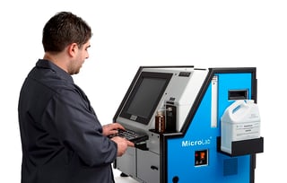
“We’ve actually redone our whole PM program around the oil analysis,” Lentsch said. It takes eight to 12 minutes for an in-house machine to complete the analysis, Lentsch said. Technicians take a sample at every single PM service, and they can retrieve the results before completing the service to determine if oil needs to be changed.
Staff also uses the machine to analyze transmission and hydraulic oil. With a backhoe, the manufacturer suggests changing hydraulic oil every 1,000 hours or three years. EWEB has lower-hour backhoes, and a quick analysis will determine whether that hydraulic oil really needs to be changed or if it can be used another year or two, Lentsch said.
Oil analysis tells the fleet more than just whether it’s ready to be changed — it can also say a lot about the condition of the vehicle. The EWEB fleet consists of about 260 vehicles, and its technicians are performing about 100 services and inspections per month. In three months, analysis has already helped technicians diagnose problems, including an injector that was leaking fuel into the vehicle, and high sodium content in the oil that was traced to an exhaust gas recirculation (EGR) system failure.
To read the complete article, please click here.
Automating oil particle analysis
Run up to 25 samples at one time
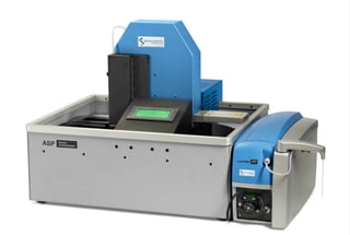 The major issue for premature failure in wind turbine gearboxes is bearing failure, which leads to gearbox failure. A wind turbine gearbox will not survive if the oil is not clean and especially if the hard ferrous particles are not removed from around the bearings
The LaserNet 230 particle counter and ferrous debris monitor has been shown to be an excellent analytical tool for end users to be able to diagnose wear faults in various machine applications such as gear boxes, engines and
transmissions.
The wear generated in a wind turbine gear box is a function of load, speed and lubricant condition. The lubricant must be correctly specified for the turbine gear box’s idealized operating load and speed and its condition must be carefully monitored in order to maintain the required lubricant film thickness in these regimes. Ever-changing wind conditions and large variations in climates make wind turbine condition monitoring extremely challenging. As a result careful continuous automated monitoring of these critical and expensive assets is required.
The National Renewable Energy Laboratory (NREL) is an existing user of the LaserNet Fines® (LNF) technology in drive train wind turbine monitoring. They have demonstrated and recommended that condition monitoring using the LNF is critical to avoiding premature failures in wind turbines.
Existing particle counter/auto sampler setups are not ideally suited to processing heavy batches of wind turbine oil samples which can also vary considerably in contamination level. Extra dilution steps for the viscosity and the contamination levels are required making them unsuitable compared to the standard clean oil hydraulic applications for which they were initially designed for.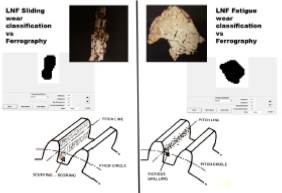
Wear particles typically found in a gearbox and how they are generated
The abnormal wear generated in any gear system typically comes from the pitch line of the gear tooth (fatigue) or the tip of the gear (severe sliding). At the pitch line, the contact is rolling so the particles will be similar to rolling contact fatigue particles. The gear contact has an increased sliding component as the root or tip is approached and the particles will show signs of sliding morphology. This morphological wear data is extremely beneficial to the end user and abnormalities in the gearboxes caused by large particle generation are easily identifiable when trends are established that can distinguish ferrous from non-ferrous material. Another critical feature of a wind turbine gearbox is the bearings are both on the low and high speed stages and any misalignment of these will induce failure.
Introducing the Knowledge Center
Want to learn more about analyzing critical fluids like lubrication oil? Check out our NEW Knowledge Center.
 Our mission at Spectro Scientific is to enable our customers to always make confident, knowledge-based decisions about their valuable assets and machinery. Whether you are testing motor oil, hydraulic fluid, fuel or coolant, we want to give you the information you need to make these decisions that could potentially affect uptime of power generation plants or the aircraft carrying military personnel. These are critical decisions that require knowledge and understanding.
To help people evaluate their options, we've created our Knowledge Center. This is a resource for customers and prospects to investigate options for testing their critical fluids such as lubricating oil, hydraulic fluids, fuel, biofuels, grease and coolants. We have also included a section that describes the various techniques for doing this testing. What are the differences between Optical Emission Spectroscopy and X-ray Fluorescence Spectroscopy? Which is right for your application?
The sections of the Knowledge Center include:
Fluid Types
- Oil
- Hydraulic fluid
- Fuel
- Biofuels
- Coolant
Analytical Techniques
- RDE Optical Emission Spectroscopy
- Particle Analysis
- Ferrous Monitoring
- Viscosity
- Infrared Spectroscopy
- X-ray Fluorescence
- Surface Acoustic Wave
Test Parameters
-
Wear
- Particle count, size, composition
- Ferrous wear
- Elemental analysis
-
Chemistry
- Oxidation, sulfation, nitration
- TAN and TBN
- Viscosity
- Elemental analysis
-
Contamination
- Water in oil
- Fuel dilution
- Soot
- Elemental
- Glycol
Resource Center
- E-guides
- Whitepapers
- Case studies
- Applications notes
- Brochures
- Datasheets
- Videos
Oil Analysis Terms (glossary of terms)
Upcoming Events
2016 Defense Maintenance & Logistics Exhibition
December 5-8, 2016
Albuquerque Convention Center
Booth # 525
OilDoc Conference and Exhibition
Jan. 24-27, 2017
Bavaria, Germany


